INTRODUCTION
 Technological improvement over the years has contributed immensely to enhancement of quality of life through various new products & Services. Another major impact of this phenomenon was the availability of these products & Services in ready to use forms. One such revolution was the pre-engineered steel buildings. Though its origin can be traced back to 1960’s its potential has been felt only during the recent years. This was mainly due to the development in technology, which helped in computerizing the design & drawing.
Though initially only off-the shelf products were available in these configuration aided by the technological development, tailor made solutions are also made using this technology in a very short duration. A recent survey by the Metal Building Manufacturers Association (MBMA) shows that about 60% of the non-residential low building in USA Pre-Engineered steel building.
The Pre-Engineered steel building industry is in its infancy in the Indian continent. The significant advantages of this form of construction over conventional structural steel and RCC construction, it is inevitable that PEB system of construction has grossly taken over the Indian construction market to a large extent.
ADVANTAGE OF PRE-ENGINEERED BUILDING SYSTEMS
[accordion clicktoclose=true scroll=true tag=h5]
[accordion-item title=”Reduced Construction Time”]Pre-Engineered buildings are a predetermined inventory of raw materials that has proven over time to satisfy a wide range of structural and aesthetic requirements.
The components are engineered beforehand and standardized. Use of these standard components reduces the engineering, production and erection time. Use of customized software for design & drafting increases the speed of the projects.
The production line is highly sophisticated having Auto welders, multi-cutting torches, shear cutting machines etc., which greatly reduce the time of fabrication of built-up components.
Roll forming machines for producing Z & C members and sheeting. having standard dimension, increases the production capacity of secondary members. use of standard accessories greatly increases the speed of production & erection.
Buildings are typically delivered in just a few weeks after approval of drawings. Foundation and Anchor Bolts are cast in parallel with manufacture of the building. Site assembly is fast, as all building components are delivered finished, ready for site bolting. Our study shows that in India the use of PEB will reduce total construction time on a project by at least 50% .This will allow faster occupancy and earlier realization of revenue. [/accordion-item]
[accordion-item title=”Lower Cost”]Due to the systems approach, there is a significant savings in design, manufacturing and site erection cost. The structural elements are shaped to follow the stress diagram of the member, thus reducing weight, cost and load to foundation. The secondary member and cladding nest together reduces transportation cost.[/accordion-item]
[accordion-item title=”Flexibility Of Expansion”]Building can be easily expanded in length by adding additional bays. Also, expansion in width and height is possible by pre-designing for future expansion.[/accordion-item]
[accordion-item title=”Large Clear Spans”]Building can be supplied to around 100-120 M clear span easily. A combination of built-up section and tubular truss helps in achieving highest economy for large span.[/accordion-item]
[accordion-item title=”Quality Control”]As buildings are manufactured completely in the factory under controlled condition, the highest product quality is assured.[/accordion-item]
[accordion-item title=”Low Maintenance”]Building are supplied with high quality paint system for cladding and steel to suit ambient condition at site, which results in long durability and low maintenance costs.[/accordion-item]
[accordion-item title=”Energy Efficient Roof and Wall Systems”]Building can be supplied with polyurethane insulated panels or fiberglass blankets insulation to achieve required ‘U’ values.[/accordion-item]
[accordion-item title=”Architectural Versatility”]Buildings can be supplied with various types of fascia, canopies, and curved eaves and designed to receive pre-cast concrete wall panels, curtain walls, block walls and other wall systems.[/accordion-item]
[accordion-item title=”Single Source Responsibility”]As the complete building package is supplied by a single vendor compatibility of all the building components and accessories is assured. This is one of the major benefits of the pre-engineered building systems.[/accordion-item]
[/accordion]
CONCEPT OF METAL BUILDING SYSTEM
A typical assembly of a simple metal building system is shown below to illustrate the synergy between the various building components as described below:
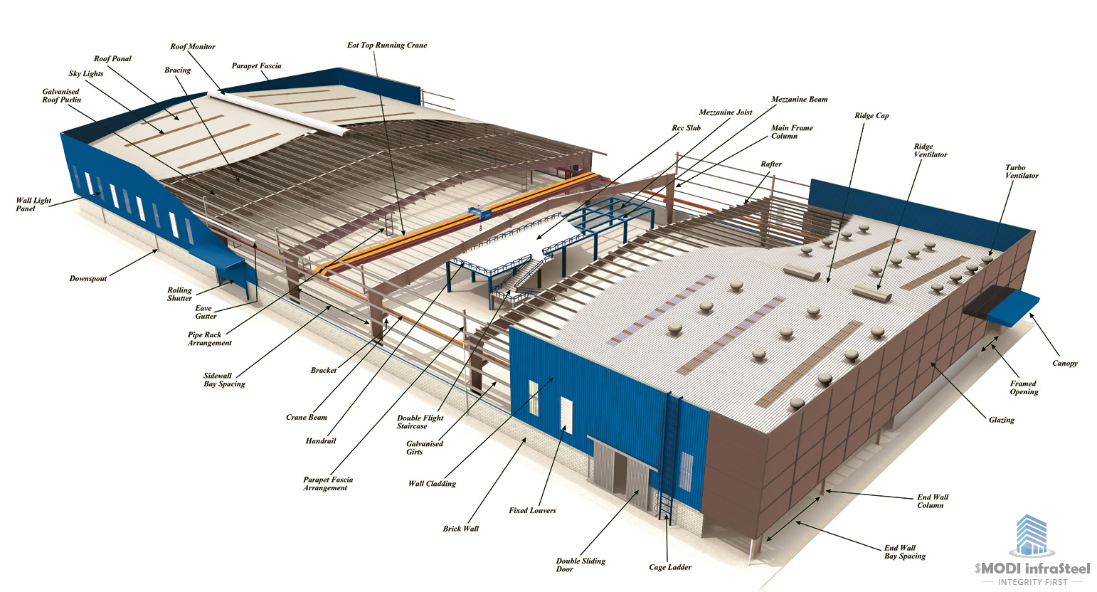
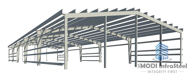
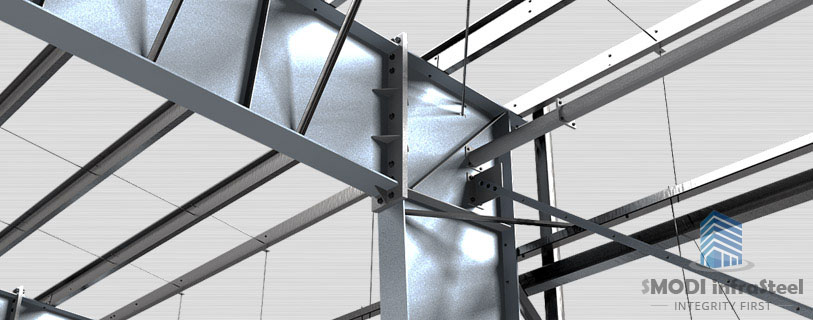
MAIN FRAMES
Moment resisting frames provide lateral stability and transfer the roof and wall loads to the foundation through anchor bolts.
SECONDARY FRAMING
Purlins and girts provide lateral bracing to the building columns and rafters preventing lateral buckling of the compression flanges.
WIND BRACING
- Roof and wall X-bracing provides longitudinal stability to the building.
- Transfers the wind load acting on building end walls to the foundation.
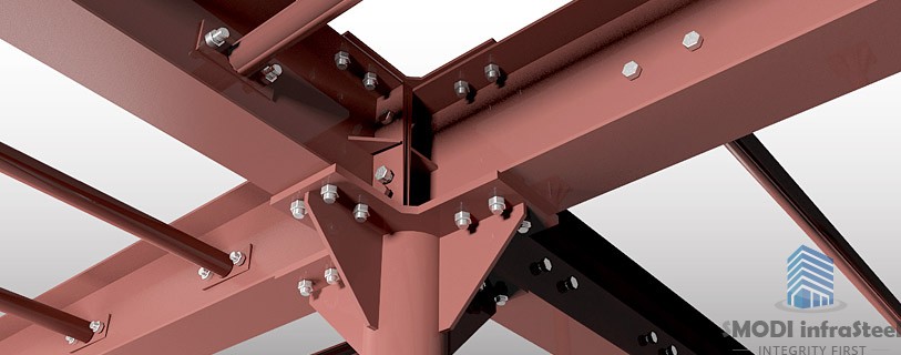
ANCHORING & ASSEMBLY HARDWARES
- Anchor bolts are the interface between steel framing to the civil foundation to transfer the forces and moments to the ground. These bolts are designed to meet the structural loading for critical condition based on designer’s choice of connection vide pinned or fixed base connection as the framing has been designed for.Assembly hardware is critical components to design and made of high strength steel. Being factory made building concept, every member has to be designed in transportable length of about 10-12 mtr. In order to assemble all the members at site it is necessary to to have proper bolted connection system which is widely designed to take up erection forces as well as post environmental as well application forces.
EXTERIOR ROOFING & CLADDING
- Provides weather tight envelops and transfers structural loads like wind and live loads to the supporting secondary framing
- Provides lateral bracing to the roof purlins and wall girts
DRAINAGE SYSTEM
- Being pitched roof, it is necessary to have properly designed drainage system vide Gutter & down pipes to transfer rain water from roof to the collection pot e.g. gutter and then discharge to the ground using down take pipes.
Due to the systems approach, the use of high strength steel, use of tapered built-up sections which are optimized by the computerized design program and the use of continues light gauge secondary steel section, there is an overall reduction in steel construction.
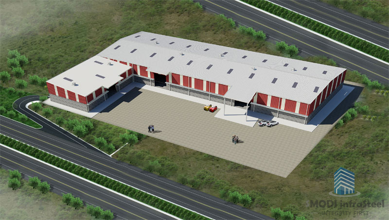
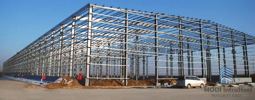
APPLICATION OF PRE-ENGINEERED STEEL BUILDINGS
- Warehouses & Logistic centers
- Factories & Manufacturing facilities
- Workshop, Show rooms & service centers
- Offices –multi-storey steel framings
- Gas Stations & petrol pump canopies
- Vehicle Parking Hangers
- Schools
- Sports and Recreational facilities
- Labor Camps
- Low Cost Housing
- Hospitals & Hotels
- Port houses
- Platform Shelters
- Multi-Level car park (MLCP)
- Aircraft hangers
- Railway station roof structure
- Aircraft hangers
PEB SYSTEMS IN INDIA
Although PEB systems are extensively used in industrial and many other non-residential constructions worldwide, it is relatively a new concept in India. These concepts were introduced to the Indian market latterly in the 1997’s with the opening up of the economy and a number of multi-nationals settings up their projects. Global PEB players have established their presence in India.
WORKING WITH PEB SYSTEMS
Following are some standard industry practices abroad, which will be adapted where required to suit Indian market conditions.
SMODI INFRASTEEL undertake turnkey project for architectural solution, design, engineering, supply & installation of steel buildings and steel structure system. Company also undertake project management services with civil foundation design work.
Site execution work is carried out through our certified builder network who undertake to install the building/structure and associated work on behalf of the company in line with company specifications and standards .Company’s qualified Engineers and designers checks & approve the final work before handover.
DESIGN OF PEB SYSTEMS
[accordion clicktoclose=true scroll=true tag=h5]
[accordion-item title=”Program Overview”]The main farming of PEB systems is analyzed by the stiffness Matrix method using in-house software. The design is based on Allowable stress Design (ASD as per the American Institute of Steel Construction (AISC) specification. The design program provides an economic and efficient design of the main frames and allows the users to utilize the program in different modes to produce the frame design satisfying the engineer’s requirements. The program analyzes and designs the frame based on the given geometry and loading and the desired load combinations as specified by the building code opted by the user. The program operates through the maximum number of cycles specified to arrive at an acceptable design.
 [/accordion-item]
[accordion-item title=”Design Cycle”]
The design cycle consists of the following steps :
- Set up section sizes and brace locations based on the geometry and loading specified for the frame design.
- Calculate moments, shears, and axial forces at each analysis point for each load combination.
- Compute allowable shear, allowable axial and allowable bending stress in compression and tension at each analysis point.
- Compute the corresponding stress ratios for shear, axial and bending based on the actual and allowable stresses and calculate the combined stress ratios.
- Decide the optimum splice locations and check to see whether the predicted sizes conform to Manufacturing & transportation constraints.
- Using the web optimization mode, arrive at the optimum web depths for the next cycle and update the member data file.
- At the end of all design cycles, an analysis is run to achieve flange brace optimization.
[/accordion-item]
[accordion-item title=”Frame Loading”]
Frame Design can handle different types of loading as described below:
- All the building dead loads due to sheeting, purlins etc., and the self weight of the frame.
- Imposed live loads on the frames with tributary reductions as applicable.
- Collateral loads such as false ceiling, light fixtures, A/C ducting loads, sprinkler systems, and any other suspended loads of similar nature.
- Wind loads input as basic wind speed or basic wind pressure will be converted to design wind pressure as per the building code specified by the user and shall be applied on different elements of the frame as per the coefficients corresponding to the user defined building code. The standard building codes like MBMA, UBC, ANSI, ASCE etc., are built in to the program and the program can automatically pick the coefficients for these codes. For special codes, however, the program offers the option for the user to input the coefficients as required.
- Seismic loads corresponding to different zone categories of various international codes can also be defined and combined with other load cases as required.
- Temperature loads can also be specified in the form of the differential temperature value in Centigrade and specifying the appropriate coefficient for thermal expansion.
- Load combinations with appropriate load factors can be specified by the user as desired.
[/accordion-item]
[accordion-item title=”Design Codes”]Following design codes are used as applicable to the project:
AISC : American Institute of Steel Construction Manual.
AISI : American Iron and Steel Institute Specifications.
MBMA : Metal Building Manufacturer’s Association Low Rise Building Systems manual.
ANSI : American National Standards Institute Specifications.
ASCE : American Society of Civil Engineers
UBC : Uniform Building Code
IS : Indian Standards.
Other codes as specified in the contract.[/accordion-item]
[accordion-item title=”Design Criteria”]
- Design Method : Allowable stress design method is used as per AISC specification
- Deflections : Unless otherwise specified, the deflections will be as per standards, which are based on MBMA and AISC criteria and standard industry practices.
- Primary Frames : Moment Resisting Plane Frames with pinned or fixed bases.
- Secondary Framing : Cold-Formed z-sections for purlins and girts designed as continuous beams spanning over rafters and columns with laps.
- Longitudinal : Wind load building and walls is transferred through.
- Stability : Roof purlins to braced bays and carried to foundations through diagonal bracing.
[/accordion-item]
[accordion-item title=”Design Software”]
Company uses the following main design software for the Design for Pre-engineered buildings:
- MBS : Metal Building Software –A design software specifically developed in the U.S. for PEB and customized to suit in-house requirement which offers complete package for estimation, Proposal drawings/Design sketches, GA Drawings, Fabrication Components drawings, Erection drawings all in one.
- Precision Plus : Design software developed in the U.S. for Estimation and design purpose.
- STAAD/STAAD-PRO/ETAB : Design software for structural analysis and design.
[/accordion-item]
[accordion-item title=”Design Process”]
The frame data is assembled based on the number of frame members, number of joints, number of degrees of freedom, the conditions of restraint and the elastic properties of the member. Based on this, the data is stored and the member section properties are computed. The overall joint stiffness matrix is generated based on the above frame data by summation of the individual stiffness matrices considering all possible displacements. The load vector is then generated based on the loading data and the unknown displacements are obtained by inverting the overall joint stiffness matrix and multiplying with the load vector.
Knowing the free joint displacement, the member and actions are obtained by back substitution. The axial, shear and bending forces are then transformed to the section neutral axis and the additional moment created by the eccentricity of the thrust is added to the moment value. These values are generated for different load combinations and the final design checks are preformed
The allowable stress values are computed as per the AISC specification with due consideration, for the web depth/thickness ratios and the flange width/thickness ratios with the appropriate correction factors as per AISC.
For computation of the allowable bending stresses, the effective un-braced lengths for each segment are used based on the brace point locations defined by the user. The effective length factor K is used for calculating the slenderness ratios in order to compute the allowable axial stresses. The coefficients for bending are calculated based on the end conditions for each member and the corresponding end moment values. The stress ratios are then computed as actual/allowable stresses and are then combined to check that the total aggregate is under unity.
The joint displacements and support reactions are reported for various load cases and combinations along with the clear heights at haunch and peak to check for clearances.
A detailed connections report is generated based on the forces acting at all the splice joint and designed as per the specification of AISC. The connections used in the super structure for all the main frame splices conform to the specifications of ASTM a 325 for High strength friction grip bolts. The anchor bolts will be of ASTM A 307 material Grade 36.[/accordion-item]
[/accordion]
SERVICEABILITY CRITERIA
Unless otherwise specified by client, the serviceability criteria are based on MBMA and standard industry practices. Following are the brief extracts from these specifications.
- Roof purlins supporting roof panels : L/150 max.
- Wall Girls supporting wall cladding : L/120 max.
- Rafter peak Deflection : L/180 max.
- Rafters supporting plastered ceiling : L/360 max. under live load.
- Bare frame drift (sway) : H/60 to H/100 max
- Bare frame drift for frames supporting cranes
- Top running Cab operated : H/240
- Top running Pendant operated : H/100
- Crane Runway Beams : L/400 max Horizontal and L/600 max vertical.
- Mezzanine supporting Beams & Joists : L/240 max. under Dead & live load and L/360 max. under L.L. only
When client requires the serviceability criteria as per IS codes, the design deflections will be complied accordingly.
MATERIAL AND FABRICATION
All materials are purchased new direct from the steel mills with certified Mill certificates complying with ASTM or equivalent specifications. Company maintains a large stock of Plates, Bars, Black coils, Galvanized coils, Sheeting coils and various building accessories required to support the production levels. All the material specifications are documented in the Company’s Specification Manual, which is an integral part of the total quality control system at factory. High strength steel having minimum yield strength of 345 Mpa is used for Primary, secondary and cladding.
The materials are subject to stringent quality control checks upon receipt at plant and only upon approval are taken into stock. The material inspection system is well documented in company Quality Control Manual and compliers with material tractability and other requirements specified in ISO9001.
The manufacture of the building is done in accordance with relevant American Codes. Welding is performed by pre-qualified welders using approved welding processes as per structural welding code AWSD1.1 published by the American Welding Society. The built-up sections are welded in an automatic CONRAC welder using submerged arc welding process. The aplice plates and other attachments are welded by the Inner shield or CO2 welding process. All butt welds are full penetration welds. Stage inspections are carried out at various stages in the manufacturing process and results documented. The welds are subject to NDT tests including Dye penetrate inspection (DPI), Magnetic particle Inspection (MPI), Ultrasonic Testing (UT) or Radiography, as required by contract specifications. A 100% visual and dimensional check is performed on all members. Manufacturing tolerances are in accordance with MBMA and AWS specifications.
The standard surface treatment for fabricated steel is mechanical wire brushing to SSPC ST3 and application of one coat of red oxide prior to a nominal dry film thickness of 25-30 microns. However company offers various types of surface preparation and epoxy paint systems to suit the corrosive conditions at site and contract requirement. Company has blast cleaning facility to achieve a white metal finish to Swedish standard SA2 ½ or SA 3 and airless spray facility to apply any specified paint system. Upon request company will recommend the optimum paint system to suit ambient conditions at site.
SITE ERECTION
Our Company provides Erection drawing procedures manual, which includes all the information required for the site assembly of the building. The erector must use to proper tools and equipment and sequence of erection as specified in company manual. The high strength bolts at the primary connections are pre-tightened to specified tension or torque as shown in the erection drawings. The method of tightening may be either using a calibrated tension or torque wrench or turn-of-the-nut method as specified in AISC Manual. Erection should always start with a braced bay and the red steel must be fully plumbed before starting cladding erection. Erection tolerances are as set forth in AISC Code of Practice except individual members are considered plumb and aligned if the deviation does not exceed 1:300 as per MBMA specifications.
BUILDING MAINTENANCE
In order to have long life cycle of the building with virtually nil maintenance cost, it is necessary to have periodic cleaning of the building. User should consult supplier for Building maintenance manual.